DIY

Atari ST TOS Replacement

Posted by admin on July 20, 2023
DIY, Retro / No Comments

I have always been an Amiga user/fanboy. After my Atari 65 XE which I got at a very early age, and before I was even aware of what the landscape of home computers was at the time, I got my first Amiga 500. Boy did I fall in love with it! Then came the Amiga 1200 and then … well … the Amigas died and I had to move on.

At the same time, the main rival of the Amiga for its price range was the Atari ST. I did not know much about the ST back then, only that it was an inferior machine when it came to graphics capabilities compared to the Amiga, and that it came with MIDI interfaces built in. Not that I knew exactly what that meant, but in my mind the Amiga was superior when it came to graphics and the Atari had more capabilities when it came to audio. Well, I was wrong on that part since I only recently discovered that the Amiga was ALSO vastly superior at the audio department, with 4 PCM channels, as opposed to 3 FM channels (based on the AY-3-8910 audio chip also used in many 8 bit computers like the Amstrad CPC and the ZX Spectrum as well as some old arcade machines like 1942 and Frogger and only had synthesis capabilities and no samples).

But enough about the history lesson, this is not what this blog post is about. Since I recently got my first Atari ST computer (an Atari MEGA ST 2) I am starting to learn a few things about it and how everything worked in Atariland. My ST came with a monochrome monitor, capable of a 640×400 black and white image and not much more. This was a very high resolution for the time and the Atari OS (TOS and GEM) looks very crisp on it, despite the complete lack of color. The only issue was that my OS was in German. While I occasionally like German and speak it a bit, I do prefer my OSes to be in English. But looking into how I would change that, I discovered that in Atariland, the OS is in ROM on the motherboard. Oh well, time to get my trusty screwdriver and open it up.

After ordering a new set of English TOS chips (TOS 1.04 which was the last version released for non Enhanced versions of the ST – the E in STE models), waiting for a few days (installing a Gotek inside the ST while waiting) they are here. Time to replace the ROMs!

Looking around inside the Mega ST, I found the 6 chips that needed replacement, next to the mighty 68000 CPU. Thankfully, the chips were not soldered to the motherboard but rather sat on sockets so they could be easily removed and replaced.

Removing them was rather simple, trying not to bend their little legs too much so that they broke. This is what they looked like after being removed.

Putting the new chips was even easier. Just align the legs and push gently and evenly down.

Power on and … nothing. No fan spinning, no Gotek getting power. Nothing. This was a scary moment until I realized that I had relied too much on the labels orientation to notice that there is a notch on the side of each chip which has to match the notch on the motherboard chip sockets.

After removing them once more, and placing them back correctly, it was a success and TOS is now in English.

So success!

Master System 2 Power Led Mod

Posted by admin on January 06, 2022
DIY, Retro / No Comments

Since we started modding the Master System 2 on the previous post, I thought I should go ahead and fix another omission of the system. A freaking power led! How would you know when the system is on without one? Well, that’s an easy fix but, since I already mentioned in the previous post that I don’t like modifying these old consoles in a irreversible way, I decided to go the extra mile and 3d print a new power button with the necessary space to let a led shine through it, so I could save the original part.
Link here: https://www.thingiverse.com/thing:4915513

So first thing is first. I already had a bunch of color cycling 5mm leds lying around from my NES mod, so I decided to use one of these as my power led for the SMS2. These are quite fun, since they automatically cycle through many different colors when power is applied.

The way you connect the led is by using 2 pins of this little thingy (which is a Voltage Regulator), which is accessible inside the Master System 2 even without removing the metal shield.

The led fits nicely inside the 3d printed power button that replaced the original one and the pins and wire come out of the side, so it does not affect its usage which is to actually, well, power the system on and on by flipping the switch below it.

And that is all you need to do. Here is a video of the result, in real life it does not shine so brightly and it looks very nice when powered on.

Master System 2 video out

Posted by admin on January 06, 2022
DIY, Retro / No Comments

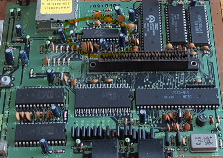
The Master System was SEGA’s answer to the Nintendo Entertainment System’s success but in the early 1980s. While it had some success, especially in Europe, the NES prevailed mostly due to more iconic characters and game designs but also due to the fact that it arrived a bit earlier in most markets. The second iteration of the Master System hardware, the Master System 2, was a cheaper version that lacked a couple of things compared to the original, namely the Sega Card and, most importantly, it could only output video using an RF output. Not ideal. Far from it actually. Funnily enough, the hardware inside can produce the signals needed for composite video and even RGB, but the necessary plugs and wiring were removed from this version.

But today we will fix that! I have all of my retro consoles connected using composite video, with a huge composite video-stereo audio switch and I wanted my newly acquired Master System 2 to be the same. Most mods I saw though required drilling holes in the original plastic body, which I did not want to do (I never do irreversible mods to these old systems). Instead, I decided to use an external small plastic hobby box, attach it on the back of the machine and keep my composite and audio outputs there. The SMS does not produce stereo sound, but I installed 2 RCA jacks connected together so I at least have the option of outputting the same audio from both.

The mod itself is pretty easy to pull off. All you need are the aforementioned RCA female plugs, one 220 uF capacitor, one 100 ohm resistor and a few wires. You need to open up the SMS2 and find the chip marked below:

We will be using one of the pins for ground (pin 1), one for the audio signal (pin 9) and one for the composite video signal (pin 20). The numbers start counting from the bottom left (marked 1) and continue counter-clockwise around the chip around the last one (marked 24).

I have used a white cable for ground, a yellow for audio and a red for video. The white cable is connected to all 3 of the RCA plugs inside the little box, the yellow to the two audio inside and the red, through the resistor and the capacitor to the video RCA as shown below:

For the capacitor, make sure that the negative touches the RCA internal while the positive goes to the motherboard (again, you also need the resistor, which I have on the chip leg itself. You can also choose to do the soldering on the back of the motherboard, where the chip sits.

You can get the cables out using the RF hole, it’s big enough. I will most likely never use RF anyway.

This is how the final system looks from the back. Works and plays great (much better than RF of course).

Tags: , , , ,


DEWATOGEL