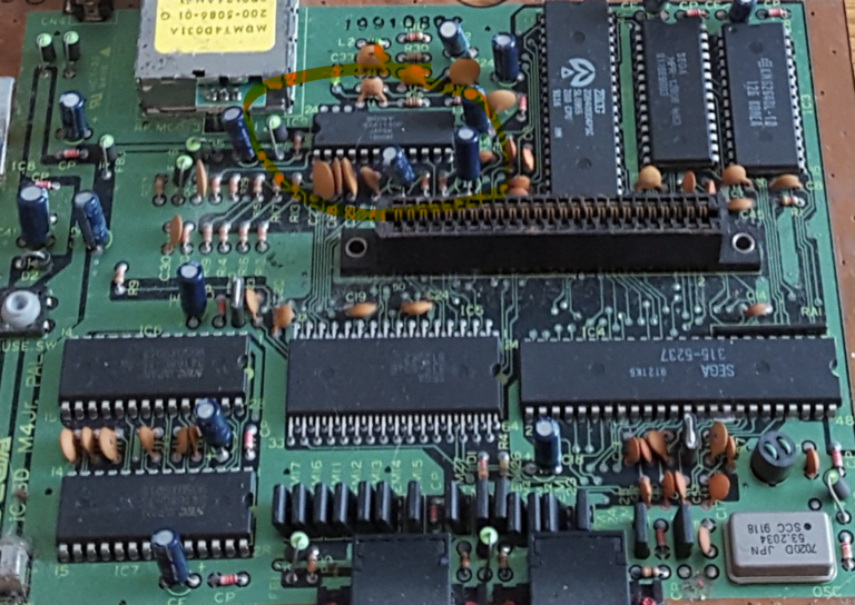
sega

Master System 2 video out

Posted by admin on January 06, 2022
DIY / No Comments

The Master System was SEGA’s answer to the Nintendo Entertainment System’s success but in the early 1980s. While it had some success, especially in Europe, the NES prevailed mostly due to more iconic characters and game designs but also due to the fact that it arrived a bit earlier in most markets. The second iteration of the Master System hardware, the Master System 2, was a cheaper version that lacked a couple of things compared to the original, namely the Sega Card and, most importantly, it could only output video using an RF output. Not ideal. Far from it actually. Funnily enough, the hardware inside can produce the signals needed for composite video and even RGB, but the necessary plugs and wiring were removed from this version.

But today we will fix that! I have all of my retro consoles connected using composite video, with a huge composite video-stereo audio switch and I wanted my newly acquired Master System 2 to be the same. Most mods I saw though required drilling holes in the original plastic body, which I did not want to do (I never do irreversible mods to these old systems). Instead, I decided to use an external small plastic hobby box, attach it on the back of the machine and keep my composite and audio outputs there. The SMS does not produce stereo sound, but I installed 2 RCA jacks connected together so I at least have the option of outputting the same audio from both.

The mod itself is pretty easy to pull off. All you need are the aforementioned RCA female plugs, one 220 uF capacitor, one 100 ohm resistor and a few wires. You need to open up the SMS2 and find the chip marked below:

We will be using one of the pins for ground (pin 1), one for the audio signal (pin 9) and one for the composite video signal (pin 20). The numbers start counting from the bottom left (marked 1) and continue counter-clockwise around the chip around the last one (marked 24).

I have used a white cable for ground, a yellow for audio and a red for video. The white cable is connected to all 3 of the RCA plugs inside the little box, the yellow to the two audio inside and the red, through the resistor and the capacitor to the video RCA as shown below:

For the capacitor, make sure that the negative touches the RCA internal while the positive goes to the motherboard (again, you also need the resistor, which I have on the chip leg itself. You can also choose to do the soldering on the back of the motherboard, where the chip sits.

You can get the cables out using the RF hole, it’s big enough. I will most likely never use RF anyway.

This is how the final system looks from the back. Works and plays great (much better than RF of course).

Tags: , , , ,